

What is in-context design?
In-context design in SolidWorks is a powerful feature that allows designers to create and modify components within the context of an assembly.
Rather than designing parts in isolation, in-context design enables the development of components directly within the assembly environment, taking into account the surrounding parts and their relationships.
Why use in-context design?
In-context design has a number of benefits. Since parts are designed around each other, it can be easier to ensure proper fit and functionality, and when in-context features are updated, the changes are reflected across all parts that use them, not only saving time, but also ensuring consistency across the design.
It’s worth noting that in-context design can become complicated and it’s easy to get confused with the references, so it is not always a suitable workflow.
Methods
There are two main methods when working with in-context design. A part file can initially be designed independently with its own sketches and features, then in-context features added or alternatively, a new file can be created within the context of the assembly and built around other geometry.
Example 1
The grey part shown below has been modelled independently, in its own part file, but the position of the holes need to be consistent with the position of the holes that already exist within the yellow part file. In order to achieve this, the part is added to the assembly and mated into position. (As the position of the holes is going to change, the part needs to have its mates added without using the holes as mate selections).
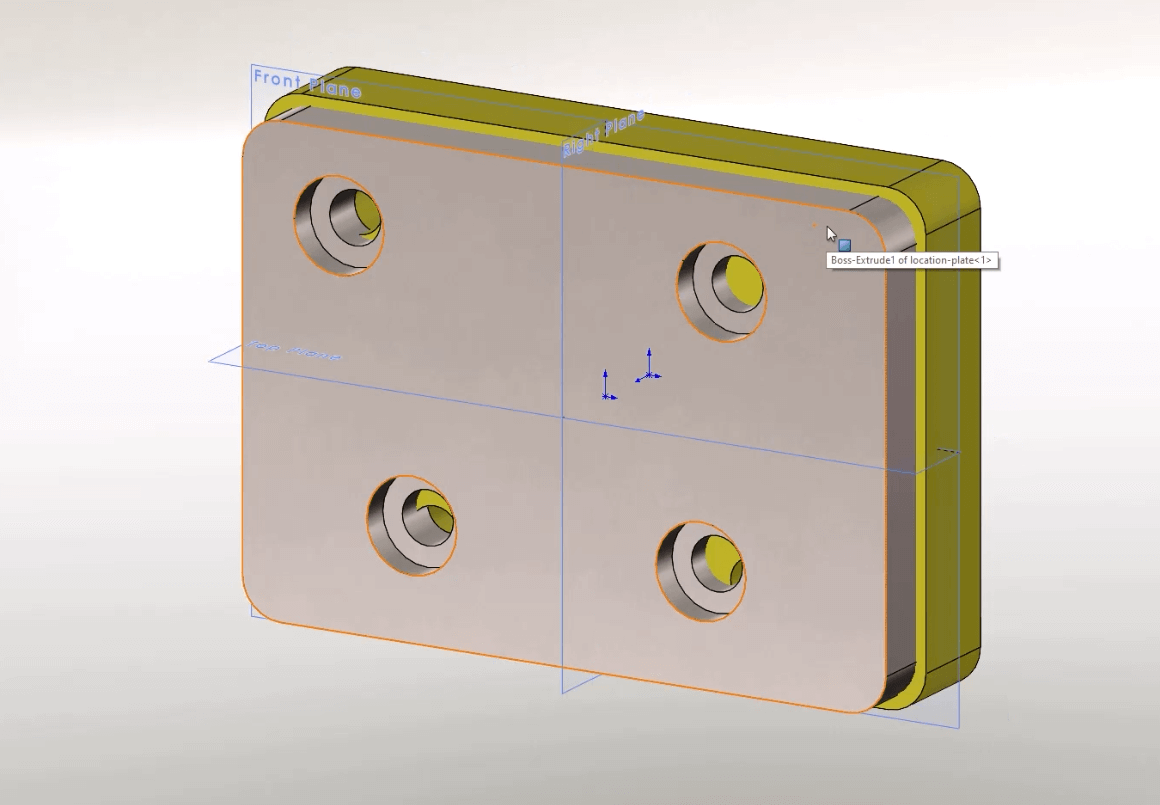
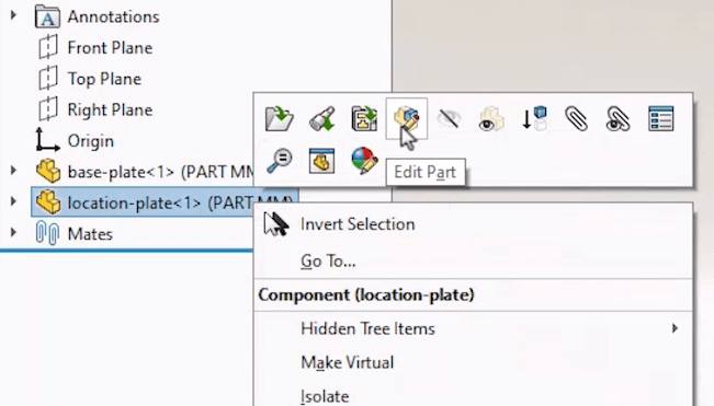
Once in position, the position of the holes in the part can be adjusted to match those of the existing part. This can be achieved by editing the grey part. Either choose to edit the grey part by right clicking and choosing edit part
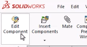
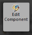
or by clicking the button on the command manager with a part selected
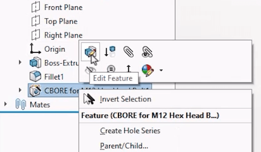
or alternatively directly editing a feature.
When you do this the interface will change slightly. By default the other components in the assembly will appear transparent and you will have access to the usual part editing features. The part name in the feature tree is highlighted in blue in the design tree too.
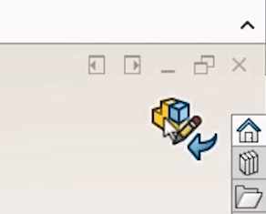
To leave the edit part mode at any point, either click the ‘edit component’ button or click the icon on the top right of the viewport.
Example 2
The second example looks at creating a brand new part file within the context of an assembly.
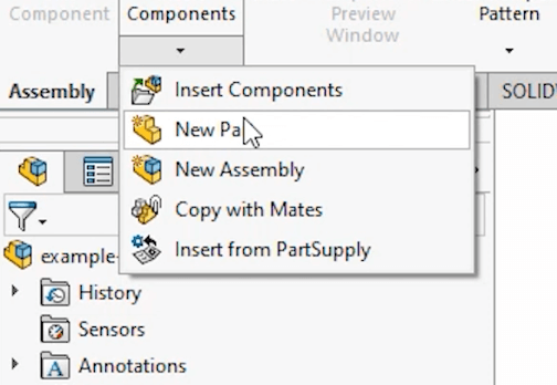
From the assembly tab, under insert components, click the new part button. SolidWorks is now looking for a selection to position the part. If a face or plane is selected, this will become the front plane of the newly created part. A sketch is also created automatically once this selection has been made.
Like the previous example, whilst we are in context of an assembly, the environment that is being worked in is now that of a part. This can be seen as the edit component button is selected in the top left of the ribbon.
From here, sketches can be created and features added just as in any other part file. The existing edges and vertices of other components can be referenced.
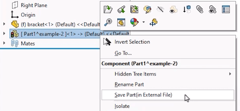
Because the part has been created within the assembly, it currently does not exist as a separate file but only exists within the assembly as a virtual component. To save the part as its own file it can be renamed and saved externally from the right mouse button menu.
Assembly Level Features
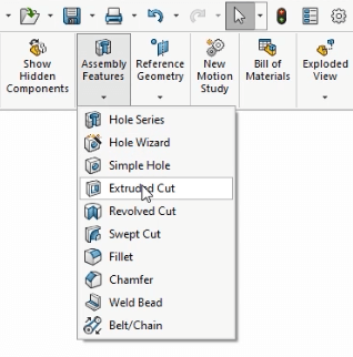
Assembly level features allow users to add features directly to components from within the assembly environment, such as holes, cuts and extrusions. These features can be applied to individual components or multiple components at the same time and can exist purely at assembly level, meaning the features are not present when the part is opened, alternatively the features can be propagated to the part level.
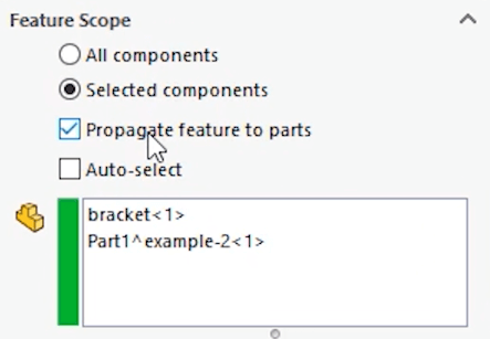
Propagation to part level is really useful as it is a great way of ensuring consistency across a range of components. However, it isn’t always required, as sometimes material is removed from a part as a secondary process, such as a hole being cut through multiple parts once assembled. Because the hole doesn’t exist when the part is manufactured, it wouldn’t want to exist in the part and the parts drawing, but it would in the assembly level drawing.
References
When in-context features are added to a part, a reference is created. This reference is added through the assembly in which the feature is added. This means that when a change is made to the “driving” part, the “related” part will update automatically.
When a reference is created, it is shown within the part file. An arrow is visible next to the feature that was edited. This is showing the in-context relationship.
It is important to note that the driven part file should always be able to refer to the assembly, and therefore the referenced part, otherwise the reference will fail. So be careful when moving or renaming files as this can break in-context references.
Finally, be careful when adding in-context relationships to not create a circular reference, where several parts all rely on each other, as this can cause rebuild issues which can be difficult to fix.


