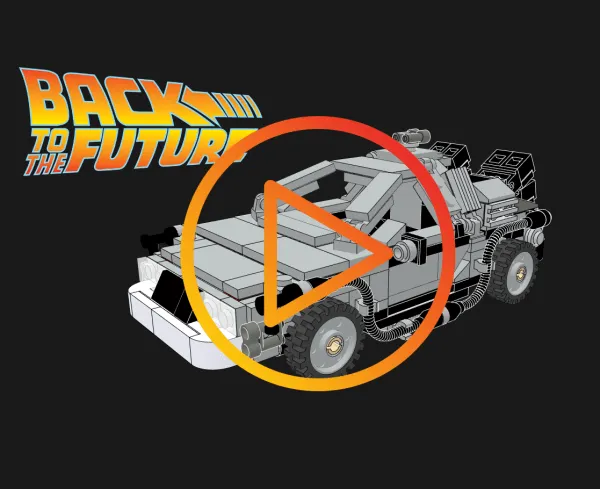
Everyone loves Lego and it has been a staple of many childhoods for what seems like forever. Over the years the sets have become more elaborate and fantastical, and so their instructions have become more important than ever. Lego instructions have always been of high quality and are clear and concise to show the assembly procedure. The downsides though are that they require a lot of printing, this set for example has 108 pages, and they are a 2D interaction which can lead to confusion when the person assembling is holding a 3D item.
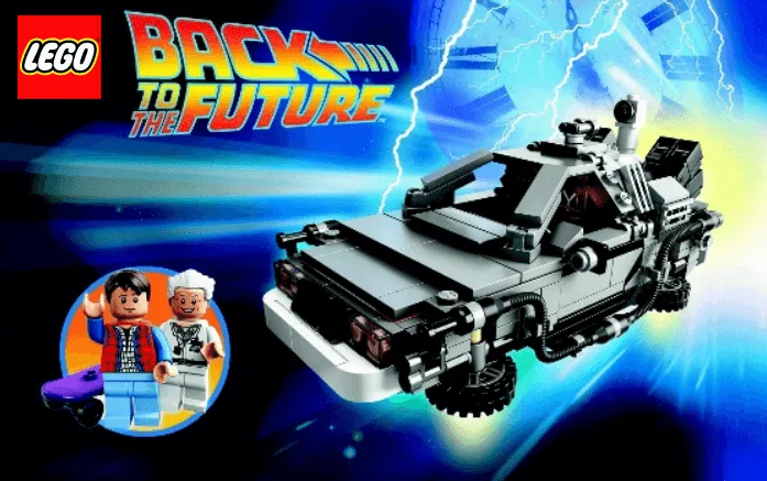
Replicating this using Cadasio was an interesting challenge that we were happy to do to see how a 3D version compares.
The first issue we faced was finding a 3D model of the Lego set. Fortunately GrabCAD came to the rescue. GrabCAD has over 8,820,000 members and is the “largest online community of professional designers, engineers, manufacturers and students”. Whilst its impressively large collection of professional CAD models is no doubt what it is best known for, it has more to offer with useful tutorials, challenges, 3D printing software and collaboration solutions.
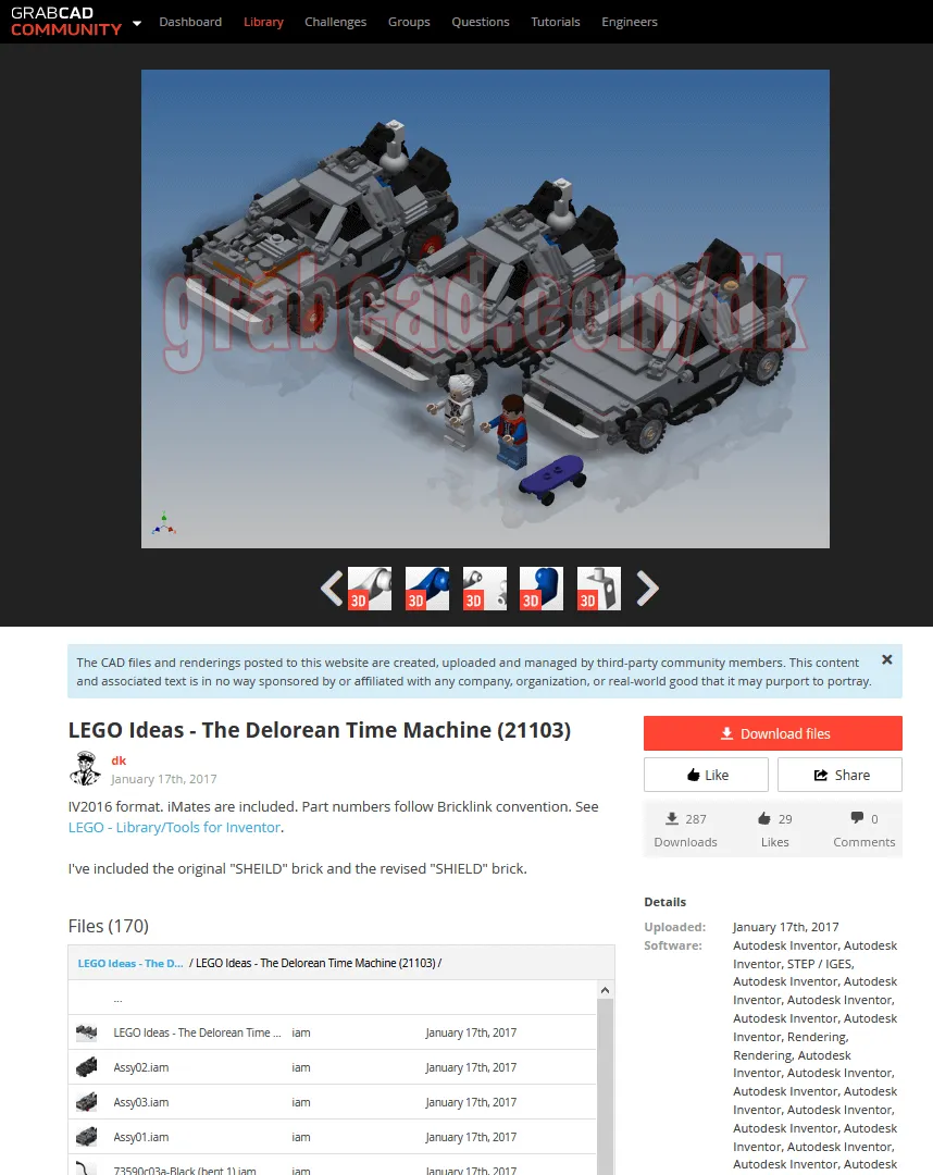
We found a very impressive and well-made Autodesk Inventor model of the Lego DeLorean, by user dk, who has a fantastic collection of other Lego sets. We got it downloaded and opened it up in Inventor, after having a quick look through the original instructions, and comparing to the model we noticed a couple of pieces missing for the instruction manuals (like the transparent stand) so we quickly added them into the assembly.
When we were ready to begin we used the Cadasio addin to create a brand-new project. This took a couple of seconds, as it converts the Inventor files, encrypts them, and uploads them to our secure servers.
When you look at Lego instructions, they all follow a very distinct style, and we identified the following key looks we wanted to replicate.
- Flat shaded.
- Black Edges – unless on a black part, in which case they are white.
- No fillets on the bricks (when compared to the downloaded Inventor model).
The first style change was easy to sort as Cadasio comes with several different render styles to choose from. Rather than setting individual components’ render style, we simply set the scenes render style to Flat.
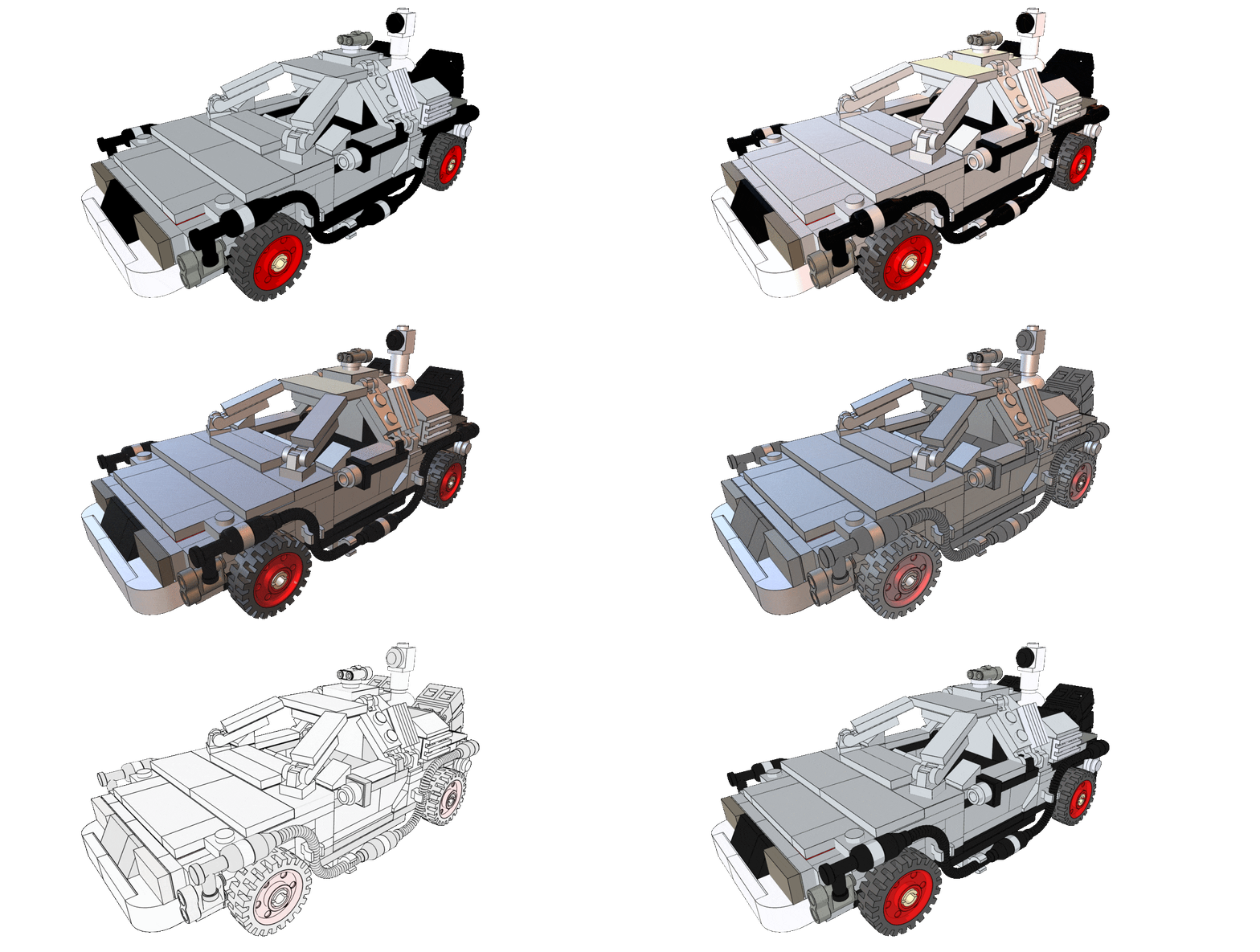
By default, edges are hidden on a Cadasio project. This is primarily done for performance reasons, however we can switch them on for the entire scene in two clicks.
At first the edges will be black, but we can change that to any colour we like, however we have identified that we only want the black parts to have a different colour. It would be quite laborious to have to select all the black parts individually so instead the select by colour tool was used. We could now set the colour those parts edges to white.
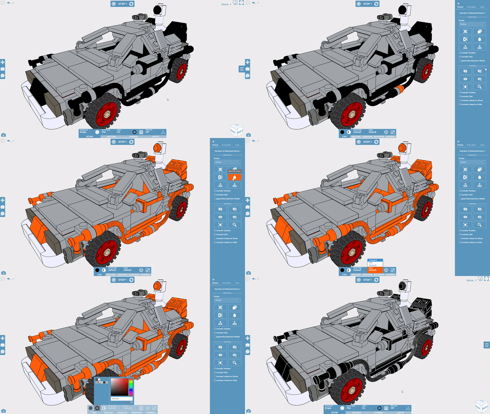
We had now changed several properties and all these changes wanted to be the default going forward, so the Start step was updated to save these changes.
On the Inventor model, and in real life, the bricks have small fillets on a lot of the edges, however these are not shown in the instructions. This is quite common practice when creating assembly instructions as often it is easier to understand and more visually appealing to have a single clean edge.
To ensure we could match this look, we needed to go back to Inventor and remove the fillets. This did not actually take long as there are many duplicates of the same bricks, and since Inventor is parametric, when we suppressed the fillets on the actual part, we could see the changes reflected instantly in the assembly.
Fortunately, although the geometry had changed, we did not need to start a new Cadasio project, instead just update our existing one. Cadasio is intelligent enough to realise that this Inventor document has already been used in an existing project so gives us an option to update.
Whilst we currently only have a single step, so we would not have lost much, I am sure you can appreciate this ability to update our technical communication when the CAD data is modified is extremely powerful as it means we won’t lose the changes we had made or have to spend time rewriting a manual.
Now we had the model exactly as we wanted, and the style was set we were ready to begin replicating the instructions. The vast majority of time you will bring in the completed assembly, as we have done here, so we actually created the instructions in reverse, but that’s no problem as we can simply reverse our steps at the end.

Using the 3D arrow options, it was easy to simply move bricks and show where they were going. This was basically repeated for all the other steps in the instructions.
Since we are working in 3D, we could approach some of the steps differently. For example, in the instructions, Step 24 shows a small, embedded image of some pieces being assembled, separately. Rather than doing that, we created steps focusing on that subassembly, before showing the whole assembly and showing their placement in context.
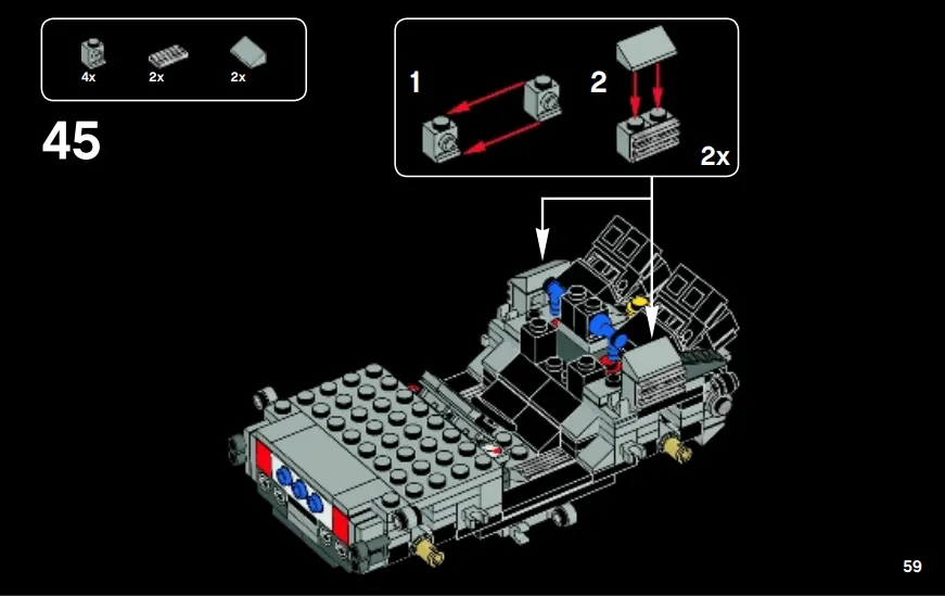
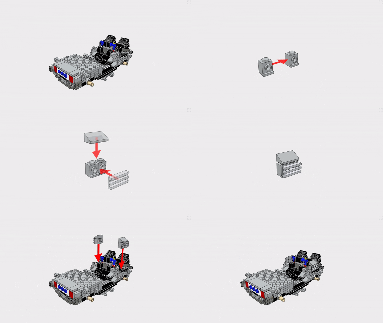
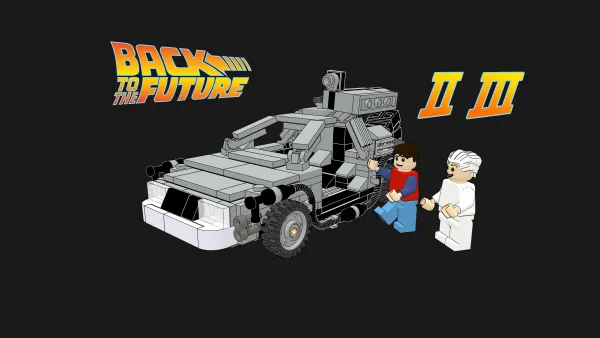
In the instructions it shows the variants of the model (for Back to the Future parts 2 and 3) one after the other at the end. Instead, we created a step which allows the user to choose which variant to see next.
We also were not too keen on having a solid black background throughout the instructions, whilst this is perfectly achievable in Cadasio, and down to personal preference, we felt a more neutral colour suited it more.
The great thing about Cadasio is that as part of creating the 3D project, we can save out 2D images, and animations. Here's the animation saved out from Cadasio, with just an intro and music added after.
However the main result of a Cadasio project is the interactive 3D instructions, check them out by clicking the image below.
If you want to create engaging, 3D, interactive content from your CAD models then try Cadasio now for free!
